 中文(繁體字)
 English (international)
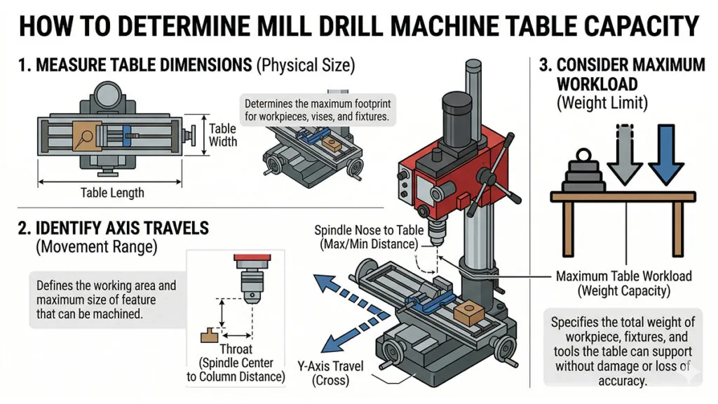
Definition of Mill Drill Table Capacity
Mill Drill Machine table capacity directly constrains the maximum workpiece size and mass that can be fixtured, positioned, and machined accurately. Selecting a machine with insufficient table capacity forces multiple setups, introducing repositioning errors and increasing cycle time.
Why it matters for Band Saw and Mill Drill Machines
The table load rating has direct implications for machining accuracy and machine longevity. Exceeding the rated load deflects the table surface from its nominal flat reference plane, creating angular errors between the spindle axis and workpiece datum. Heavy workpieces also impose additional load on the cross-slide feed screws and column dovetail ways, accelerating wear and increasing backlash over time in the Mill Drill Machine.
From an operational planning perspective, table capacity should be evaluated against the full range of workpieces in the production mix, not just the most common part. A Mill Drill Machine with marginal table capacity for the largest workpieces in the production schedule will consistently constrain scheduling flexibility. Confirming adequate X travel, Y travel, T-slot spacing, and load capacity before machine selection prevents capacity bottlenecks during production.
FAQ
How should Mill Drill Machine table capacity be evaluated when planning fixtures for large workpieces?
Evaluating Mill Drill Machine table capacity for large workpiece fixturing requires assessing four parameters: table travel range, T-slot spacing, load rating, and overhang limits. The workpiece must fit within the X-Y travel envelope with sufficient clearance for clamps and toolpath approach distances, typically 20-30mm on each axis boundary. T-slot spacing must accommodate the vise or clamp footprint at a minimum of two T-slots per fixture element for secure clamping. Load rating should include workpiece weight, fixture weight, and dynamic cutting forces combined. For workpieces approaching the Mill Drill Machine table capacity limit, use a dial indicator to verify table flatness under load before committing to precision features, as deflection may exceed workpiece tolerance requirements.
What T-slot configurations are most compatible with standard workholding on a Mill Drill Machine table, and how does this relate to table capacity?
Standard Mill Drill Machine table configurations typically feature three T-slots at 63mm or 80mm spacing with 12mm or 14mm slot widths, matching the bolt patterns of most commercial 100-125mm machine vises and standard clamp sets. This compatibility directly affects table capacity utilization by enabling rapid setup without custom fixturing. Non-standard T-slot widths require adapter keys or custom T-bolts, adding setup time and potential for clamping errors. When assessing Mill Drill Machine table capacity for production work, confirm that T-slot spacing accommodates dual-contact clamping on the vise base, distributing workholding forces across two slots rather than one, reducing localized table deflection and improving workpiece stability during milling cuts.
How does Mill Drill Machine table capacity affect achievable positional accuracy across the full X-Y travel range?
Mill Drill Machine table capacity and positional accuracy are related through the quality of the feed screw and nut assemblies that drive X-Y movement. At the extremes of the travel range, feed screw deflection and accumulated backlash are typically greater than at the center of travel, causing positional errors that increase toward the table limits. Standard benchtop Mill Drill Machines achieve 0.02-0.05mm positional accuracy at the center of travel, with errors potentially reaching 0.08-0.15mm near the travel extremes. For precision work requiring consistent accuracy across the full Mill Drill Machine table capacity, calibrate the DRO at multiple points along each axis and apply compensating offsets in the machining program to correct for travel-dependent positional variation.