 中文(繁體字)
 English (international)
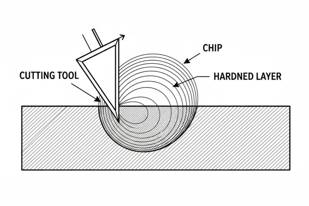
Definition of Work Hardening Effect
Why It Matters for Band Saw and Mill Drill Machines
FAQ
How does mill drill machine work hardening effect influence optimal cutting parameters for austenitic stainless steel machining?
Mill drill machine work hardening effect requires reduced feed rates and positive rake angles when machining austenitic stainless steel to control strain hardening intensity. Typical cutting speeds range from 60-80 SFPM with feed rates of 0.003-0.005 IPT for roughing operations, using sharp carbide tools with chip breakers. The material's tendency to work harden rapidly demands continuous chip removal without dwelling, as interrupted cuts or tool rubbing creates severely hardened layers that damage subsequent passes. Coolant application must be consistent and abundant to manage heat generation from the increased cutting forces associated with work hardening. Tool path strategies should minimize direction changes and avoid multiple passes over the same area. Depth of cut should be sufficient to penetrate below the previously work-hardened layer, typically 0.060-0.100 inches minimum for roughing. These parameter adjustments extend tool life by 40-60% compared to standard steel cutting approaches while maintaining acceptable surface finish quality.
What relationship exists between mill drill machine work hardening effect and tool wear progression during extended production runs?
The mill drill machine work hardening effect accelerates tool wear through a progressive feedback mechanism where increasing material hardness generates higher cutting forces and temperatures. Initial tool wear creates slight edge dulling that causes more rubbing action rather than clean shearing, intensifying work hardening in subsequent passes. This hardened layer then increases abrasive wear on the tool's flank face, creating a cycle of deteriorating cutting conditions. Monitoring flank wear land development provides early indication of excessive work hardening, with measurements exceeding 0.015 inches typically signaling the need for parameter adjustment or tool replacement. Coated carbide tools with TiAlN or AlCrN coatings demonstrate superior resistance to the combined thermal and mechanical stresses from machining work-hardened materials, extending useful tool life by 2-3 times compared to uncoated tools. The relationship between work hardening and wear is non-linear, with tool degradation accelerating rapidly once critical wear thresholds are exceeded, making proactive tool management essential for maintaining consistent part quality.
Which mill drill machine work hardening effect mitigation strategies prove most effective for nickel-based superalloy machining operations?
Effective mitigation of mill drill machine work hardening effect in nickel superalloys requires integrated approaches combining tool selection, cutting parameters, and thermal management. Ceramic or CBN cutting tools operating at surface speeds of 150-250 SFPM with feed rates of 0.004-0.006 IPT minimize work hardening by maintaining continuous cutting action without excessive pressure. Positive rake angles of 5-10 degrees reduce cutting forces while sharp cutting edges prevent material smearing that intensifies strain hardening. High-pressure coolant delivery at 1000-1500 PSI directed at the cutting zone manages chip evacuation and thermal effects simultaneously. Trochoidal milling strategies maintain constant tool engagement while distributing heat across larger tool areas, reducing localized work hardening. Limiting axial depth of cut to 0.030-0.050 inches with radial engagement of 10-15% tool diameter allows efficient chip formation without generating excessive subsurface deformation. These combined strategies can reduce work hardening depth from 0.020 inches to less than 0.005 inches while improving surface finish and maintaining dimensional tolerances within 0.001 inches.