 中文(繁體字)
 English (international)
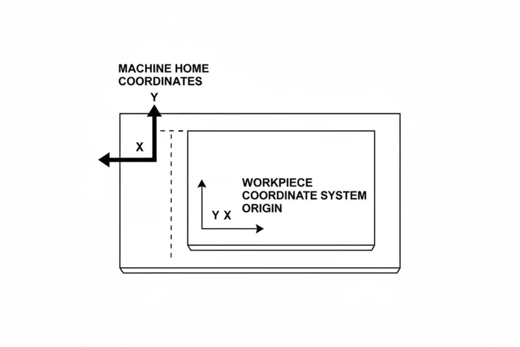
Definition of Work Coordinate System Setting
Why It Matters for Band Saw and Mill Drill Machines
FAQ
How does mill drill machine work coordinate system setting procedure differ when using edge finders versus electronic probe systems for workpiece location?
Mill drill machine work coordinate system setting with edge finders requires manual tool positioning and calculator-based offset computation, while electronic probes automate measurement and offset calculation. Edge finder procedures involve spinning the edge finder in the spindle at 800-1000 RPM, then carefully approaching the workpiece edge until the indicating portion deflects, signaling contact with the workpiece surface. The operator notes the machine position display, adds or subtracts half the edge finder diameter (typically 0.100 inches), and manually enters this calculated value as the work offset. This process repeats for each axis, requiring 10-15 minutes total setup time with accuracy depending on operator skill, typically achieving ±0.001 inches repeatability. Electronic probe systems use a touch-trigger probe with wireless signal transmission that automatically records contact position when the probe stylus deflects. Pre-programmed probe cycles position the probe, approach the workpiece at controlled feed rates, detect contact, retract, and calculate work offsets internally without manual calculation. Multiple measurements in each axis provide averaged results with statistical confidence intervals. The mill drill machine work coordinate system setting accuracy improves to ±0.0002 inches with probe systems while reducing setup time to 3-5 minutes. Probes enable complex feature location including angled surfaces, bore centers, and curved edges that edge finders cannot accurately measure.
What relationship exists between mill drill machine work coordinate system setting accuracy and achievable feature-to-feature positional tolerances in multi-operation parts?
The relationship between mill drill machine work coordinate system setting accuracy and feature-to-feature positional tolerances follows an error propagation model where setting errors add to machining errors in determining total positional deviation. When multiple features reference the same work coordinate system, their relative positions depend primarily on machine accuracy and programmed dimensions, with work coordinate system setting errors affecting all features equally and canceling out in relative position calculations. However, features machined in different setups with independent work coordinate system settings accumulate separate setting errors that combine to affect relative position accuracy. For example, if two setups each have ±0.001 inch coordinate system setting uncertainty, features spanning both setups may deviate by ±0.0014 inches (root-sum-square error combination) from design intent. To maintain feature-to-feature positional tolerances of ±0.002 inches across multiple mill drill machine setups, work coordinate system setting accuracy must be 2-3 times tighter, requiring ±0.0005-0.0007 inch setting precision. Critical positional relationships should be machined within single setups whenever possible to eliminate coordinate system setting error propagation. When multi-setup operations are unavoidable, common reference features (precision pins, fixed fixture locations) should be incorporated and measured in all setups to verify coordinate system alignment within acceptable limits.
Which mill drill machine work coordinate system setting verification methods provide highest confidence before executing expensive material removal operations?
High-confidence mill drill machine work coordinate system setting verification combines multiple independent measurement approaches before committing to material removal. The primary verification method involves dry-running the CNC program in single-block mode with the tool positioned 0.050-0.100 inches above the programmed Z-zero, visually confirming tool path alignment with workpiece features. This technique reveals gross offset errors exceeding 0.020 inches before any cutting occurs. Secondary verification uses a precision dial indicator mounted in the spindle to physically measure distances from the work coordinate system origin to critical workpiece features, comparing measured values against programmed dimensions with expected agreement within ±0.001 inches. For maximum confidence, especially with expensive materials, an additional verification involves programming a light scoring pass at 10-20% programmed depth around the part perimeter at very low feed rates (2-4 IPM). This creates visible witness marks showing actual tool path location without significant material removal, allowing final verification before full-depth machining. The mill drill machine work coordinate system setting can be adjusted if scoring reveals errors, then confirmed with a second light pass before proceeding to production parameters. Electronic probe systems offer automated verification by re-measuring offset-defining features after initial setting, comparing measured positions to programmed values and flagging discrepancies exceeding tolerance before machining begins. These combined verification approaches reduce setup errors to less than 1% of production runs.