 中文(繁體字)
 English (international)
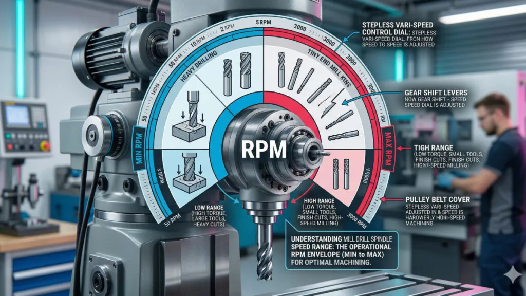
Definition of Mill Drill Spindle Speed Range
Proper speed selection directly affects tool life, surface finish quality, and material removal rate. Operating outside the optimal range accelerates tool wear, generates excess heat, and risks workpiece damage. Understanding the full spindle speed range of your Mill Drill Machine is essential for matching tooling to material requirements across the full range of drilling and milling operations.
Why it matters for Band Saw and Mill Drill Machines
Speed selection directly influences cutting tool performance and longevity. Carbide end mills typically require higher surface speeds (300-500 SFM in aluminum) while high-speed steel tooling performs optimally at lower speeds (60-100 SFM in mild steel). Operating a Mill Drill Machine outside the recommended speed range for a given tool-material combination causes premature tool failure, poor surface finish, and workpiece rejection.
From a maintenance perspective, the spindle drive system requires regular attention to sustain accurate speed delivery. Belt-driven systems need periodic belt inspection and tension adjustment, while electronic variable speed drives require monitoring of motor temperature and control electronics. Consistent spindle speed range performance is a key indicator of overall Mill Drill Machine health.
FAQ
How should the Mill Drill Machine spindle speed range be selected when transitioning between aluminum and mild steel operations?
When transitioning between aluminum and mild steel on a Mill Drill Machine, spindle speed range selection requires recalculation based on material-specific cutting speeds. Aluminum alloys support cutting speeds of 200-500 SFM, requiring significantly higher RPM for small-diameter tooling. Mild steel requires 80-120 SFM for HSS tooling or 200-350 SFM for carbide. Using the formula RPM = (CS x 12) / (pi x D), a 10mm HSS end mill in mild steel operates at approximately 300-450 RPM, while the same tool in aluminum requires 750-1,500 RPM. Failing to adjust the Mill Drill Machine spindle speed range when changing materials accelerates tool wear and compromises surface finish. Always verify the selected speed against tooling manufacturer specifications before commencing cuts.
What factors limit the upper end of the Mill Drill Machine spindle speed range during high-speed operations?
The upper limit of the Mill Drill Machine spindle speed range is constrained by mechanical and thermal factors. Spindle bearing design sets the maximum safe RPM, beyond which bearing temperature rises sharply and premature failure occurs. Drive belt capacity in stepped pulley systems limits peak speed, while motor power determines whether maximum RPM is sustainable under cutting loads. Dynamic balance of the spindle and toolholder assembly becomes critical at high speeds, as minor imbalances generate vibration that degrades surface finish and accelerates bearing wear. For operations at the upper end of the Mill Drill Machine spindle speed range, use balanced collet holders, verify runout is below 0.01mm TIR, and ensure adequate lubrication is maintained in the spindle head.
How does the available Mill Drill Machine spindle speed range affect tooling selection for stainless steel operations?
Stainless steel machining imposes specific demands on Mill Drill Machine spindle speed range selection due to the material's work-hardening tendency and low thermal conductivity. Recommended cutting speeds for austenitic stainless are 50-80 SFM with HSS tooling and 150-250 SFM with coated carbide. For a 10mm carbide end mill, this translates to approximately 500-800 RPM, placing most benchtop Mill Drill Machines within an accessible speed tier. The critical requirement is avoiding speed variation during cutting, as inconsistent RPM promotes work hardening in the stainless surface. Ensure the selected Mill Drill Machine spindle speed is achievable under load, not just at no-load conditions, and apply cutting fluid continuously to manage heat generation throughout the operation.