 中文(繁體字)
 English (international)
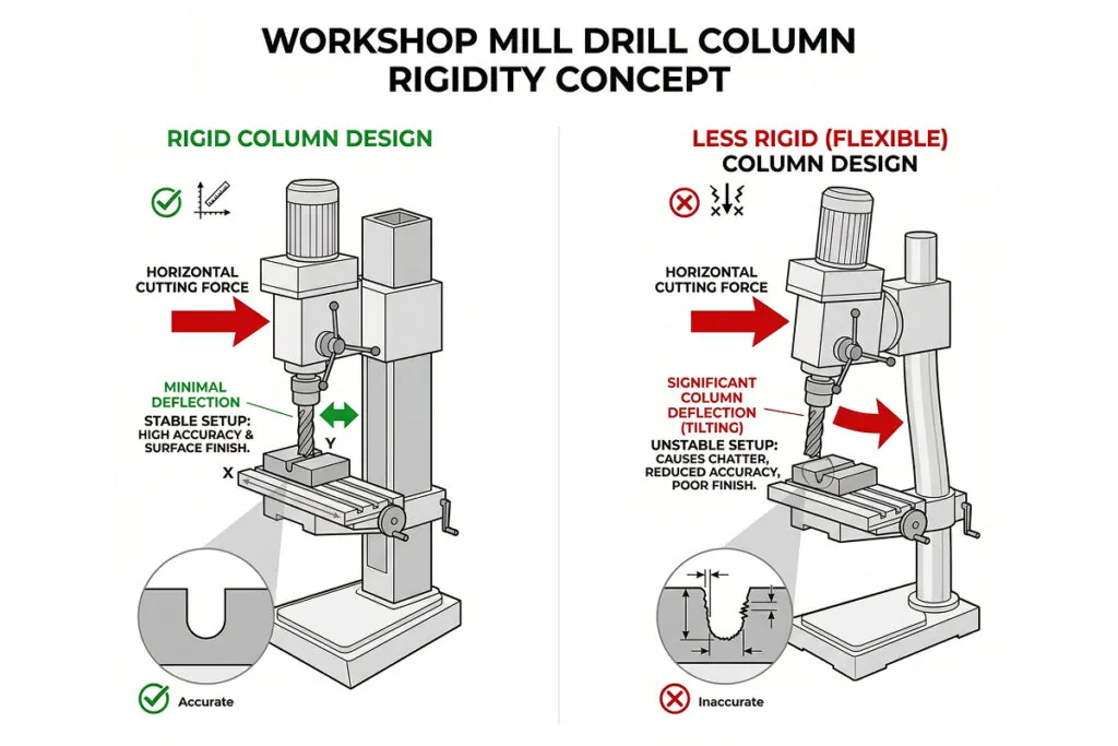
Definition of Mill Drill Column Rigidity
A rigid column resists deflection under the lateral cutting forces generated during milling operations, maintaining consistent tool-to-workpiece positioning throughout the cut. Insufficient Mill Drill Machine column rigidity manifests as chatter, taper in bored holes, and dimensional variation across the workpiece. Round column designs allow head rotation but offer lower torsional stiffness compared to dovetail column configurations. Column rigidity has greater operational impact during milling than drilling, as milling generates sustained lateral forces that drilling does not.
Why it matters for Band Saw and Mill Drill Machines
Column rigidity also determines the machine's tolerance to interrupted cuts and varying chip loads. Casting inclusions, cross-holes, and material transitions generate impact forces that a rigid column absorbs without resonance. A compliant column amplifies these transient forces into vibration, accelerating tool wear and producing poor surface finish on Mill Drill Machine workpieces.
From a maintenance perspective, column rigidity degrades over time due to wear in the head clamping mechanism, loosening of column mounting bolts, and wear in the dovetail or round column guide surfaces. Periodic inspection of head clamping torque, column mounting integrity, and vertical slide play ensures sustained rigidity performance. Any increase in chatter or dimensional variation should prompt inspection of the Mill Drill Machine column assembly before attributing the cause to tooling or fixturing.
FAQ
How does Mill Drill Machine column rigidity affect achievable depth of cut during face milling operations?
Mill Drill Machine column rigidity directly limits the maximum practical depth of cut during face milling by constraining how much lateral force the structure can absorb before deflection becomes significant. For a typical round-column Mill Drill Machine, lateral deflection under milling load can reach 0.05-0.15mm at aggressive parameters, causing dimensional error and surface finish degradation. Dovetail column designs typically exhibit 40-60% greater lateral stiffness, supporting deeper cuts at equivalent accuracy. Limit radial engagement to 40-50% of cutter diameter and axial depth to 0.3-0.5mm per pass when Mill Drill Machine column rigidity is uncertain. Monitor for chatter onset, which indicates the deflection limit has been reached, and reduce depth of cut accordingly.
What maintenance procedures help sustain Mill Drill Machine column rigidity over extended service periods?
Sustaining Mill Drill Machine column rigidity over time requires systematic attention to the head clamping mechanism, vertical slide, and column mounting interface. The head lock lever and clamping bolts should be inspected for wear and verified to achieve full clamping torque at each use. Dovetail slide gibs require periodic adjustment to eliminate play without binding, checked by measuring head displacement under a 50N lateral load with a dial indicator. Column base mounting bolts should be re-torqued annually or after any machine relocation. For round-column Mill Drill Machines, inspect the column surface for wear grooves and regrease bearing surfaces quarterly. Any measurable increase in spindle-to-table distance variation during head traversal indicates reduced column rigidity requiring immediate investigation.
How does Mill Drill Machine column rigidity compare between round column and dovetail column designs for production milling applications?
Round column and dovetail column Mill Drill Machines differ fundamentally in rigidity characteristics relevant to production milling. Round column designs allow full 360-degree head rotation for angled operations but offer lower torsional stiffness and require re-tramming the head whenever vertical position is changed. Dovetail column configurations constrain head movement to the vertical axis, providing significantly greater lateral and torsional stiffness under milling loads. For production milling applications requiring consistent tolerances of plus or minus 0.05mm or better, dovetail column Mill Drill Machines are the preferred choice. Round column machines remain suitable for drilling-dominated work where lateral forces are minimal. Selecting the appropriate Mill Drill Machine column configuration at the procurement stage avoids structural limitations that compromise milling accuracy in production environments.