 中文(繁體字)
 English (international)
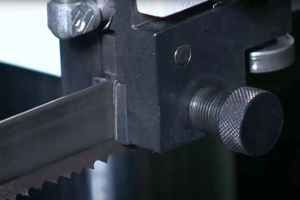
Definition of Band Saw Guide System
Guide systems are available in roller bearing, ceramic insert, and carbide block configurations, each offering different performance characteristics suited to specific blade speeds, material types, and production volumes. Proper guide positioning, typically 3 to 5 mm above the workpiece, is essential for accurate and stable cuts throughout the machine's service life.
Why it matters for Band Saw and Mill Drill Machines
The choice of guide type also affects maintenance frequency and operating cost. Roller bearing guides are well-suited for high-speed cutting of non-ferrous metals, while ceramic and carbide insert guides offer greater durability when cutting harder or more abrasive workpieces. All guide types require periodic inspection and replacement to prevent blade damage from contact with worn surfaces.
In OEM and production-grade band saws, guide systems are often integrated into adjustable assemblies that allow rapid repositioning between jobs. Misaligned or worn guides are a leading cause of premature blade failure; monitoring guide wear as part of a scheduled maintenance program significantly reduces unplanned downtime and extends blade life.
Related Terms
blade deflectionblade kerf
blade tension
cutting tolerance
blade speed range
frame rigidity
FAQ
What types of band saw guides are used in OEM machines?
Band saw guide systems used in OEM machines fall into three primary categories: roller bearing guides, ceramic insert guides, and carbide block guides. Roller bearing guides are the most common in general-purpose and high-speed applications due to their low friction and compatibility with a wide range of blade widths. Ceramic insert guides provide excellent heat resistance and require no lubrication, making them well-suited for dry cutting applications. Carbide block guides offer maximum rigidity and wear resistance, typically specified on production band saws cutting ferrous materials at sustained feed rates. Each band saw guide system type requires specific adjustment procedures to maintain correct blade support clearance and minimize lateral deflection during operation.
How should a band saw guide system be adjusted to maintain cut accuracy?
Proper adjustment of a band saw guide system requires positioning guide bearings or inserts as close to the blade sides as possible without contact when the blade is at rest, typically a clearance of 0.01 to 0.05 mm. The back thrust bearing should contact the blade only under cutting load. After setting guide clearances on the band saw, verify alignment by running the machine unloaded and confirming the blade tracks centrally on the wheels. Re-check settings whenever a new blade is installed or blade width changes. Guides set too tight accelerate blade side wear; guides set too loosely permit lateral drift and degrade cut accuracy across the full cross-section of the workpiece.
What are the symptoms of a worn or misaligned band saw guide system?
A worn or misaligned band saw guide system typically presents several observable symptoms. The most common indicator is curved or inconsistent cuts despite correct blade tension and feed rate. Excessive blade noise or vibration at the guide contact zone suggests worn bearings or incorrect clearance. Accelerated blade breakage near the gullet area often points to lateral overloading from improperly set guides on the band saw. Visible scoring on the blade body or unusual heat discoloration at guide contact points confirms insufficient clearance. Regular visual inspection at blade changes and scheduled measurement of guide wear surfaces are recommended to identify deterioration before it causes blade damage or cut quality loss.