 中文(繁體字)
 English (international)
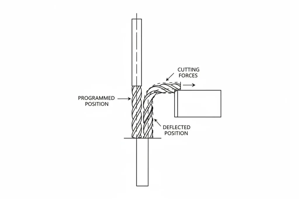
Definition of Tool Deflection Compensation
Why It Matters for Band Saw and Mill Drill Machines
FAQ
How does mill drill machine tool deflection compensation calculation differ between end milling and drilling operations?
Mill drill machine tool deflection compensation requires distinct calculation approaches for end milling versus drilling due to fundamental differences in force application and tool geometry. End milling operations generate radial cutting forces perpendicular to the tool axis, causing lateral deflection that affects wall position and pocket dimensions. Compensation calculations use beam deflection equations incorporating tool length, diameter, modulus of elasticity, and radial force magnitude, with typical deflection values ranging from 0.001-0.010 inches depending on setup rigidity. Drilling operations produce primarily axial forces along the tool centerline with minimal lateral deflection, but torsional deflection and drill wandering require different compensation strategies. Drill deflection compensation focuses on entry point accuracy and hole straightness through reduced feed rates and pilot hole pre-drilling rather than lateral position adjustment. The mill drill machine controller must switch compensation algorithms based on operation type, with milling compensation adjusting X-Y coordinates while drilling compensation manages Z-axis feed characteristics and pre-positioning accuracy to maintain hole location tolerances within 0.002 inches.
What factors determine the accuracy limitations of mill drill machine tool deflection compensation in production environments?
Accuracy limitations of mill drill machine tool deflection compensation stem from variations in cutting forces, tool condition degradation, and model prediction errors during production. Cutting force fluctuations caused by material hardness variations, interrupted cuts, or chip loading changes create dynamic deflection that differs from steady-state compensation values by 15-30%. Tool wear progression alters effective cutting geometry and force distribution, gradually shifting actual deflection away from initial compensation parameters until recalibration becomes necessary. Temperature effects on tool modulus of elasticity and thermal expansion introduce additional errors of 0.001-0.003 inches per foot of tool extension as the tool heats during cutting. The mill drill machine tool deflection compensation model accuracy depends on precise knowledge of tool dimensions and material properties, with measurement uncertainties of 5-10% in length or diameter translating to proportional compensation errors. Real-time force monitoring systems can reduce these limitations by providing continuous deflection updates, but implementation costs and computational requirements limit widespread adoption. Practical compensation accuracy typically achieves 60-80% error reduction compared to uncompensated machining, with residual errors of 0.001-0.004 inches remaining in challenging applications.
Which mill drill machine tool deflection compensation strategies work best for thin-walled aluminum component machining where cutting forces vary significantly?
Effective mill drill machine tool deflection compensation for thin-walled aluminum components requires adaptive strategies that respond to varying cutting forces throughout the machining cycle. Progressive roughing toolpaths with gradually reducing radial engagement from 50% to 20% of tool diameter minimize force variations while controlling deflection magnitude. Climb milling orientation provides more consistent chip formation and force direction compared to conventional milling, improving compensation accuracy by maintaining predictable deflection patterns. Tool selection favoring reduced helix angles of 30-35 degrees and 3-4 flutes distributes cutting forces more evenly around the tool circumference, reducing peak lateral deflection. High-frequency dynamic compensation using accelerometer feedback can track force variations at 1000 Hz sampling rates, adjusting tool position in real-time to maintain tolerances within 0.002 inches despite changing cutting conditions. Adaptive feed rate control linked to cutting force sensors reduces feed by 30-50% when force spikes occur, preventing excessive deflection during difficult cutting situations. These integrated approaches achieve dimensional accuracy of ±0.003 inches on thin-wall features while maintaining surface finish below 63 Ra microinches in aluminum alloys.